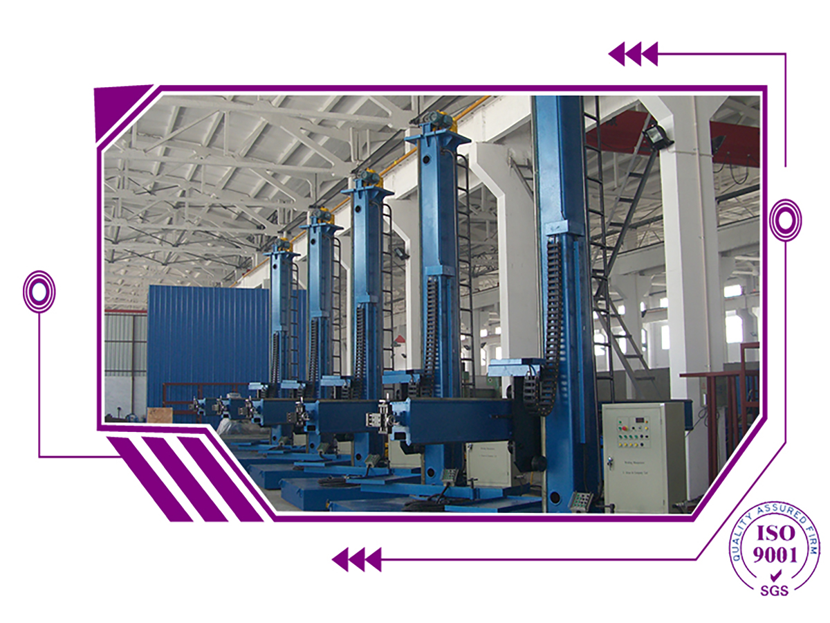
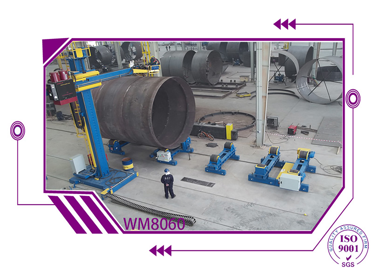
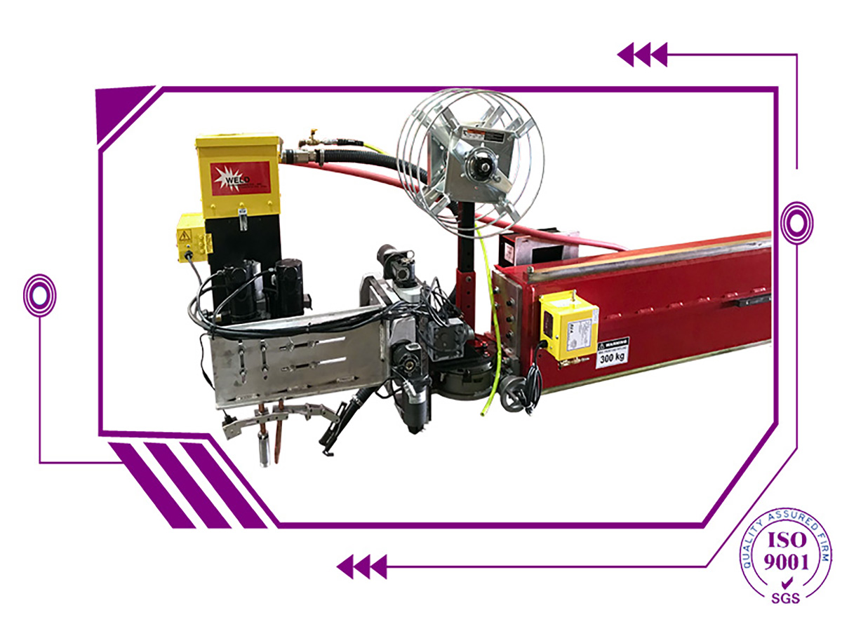
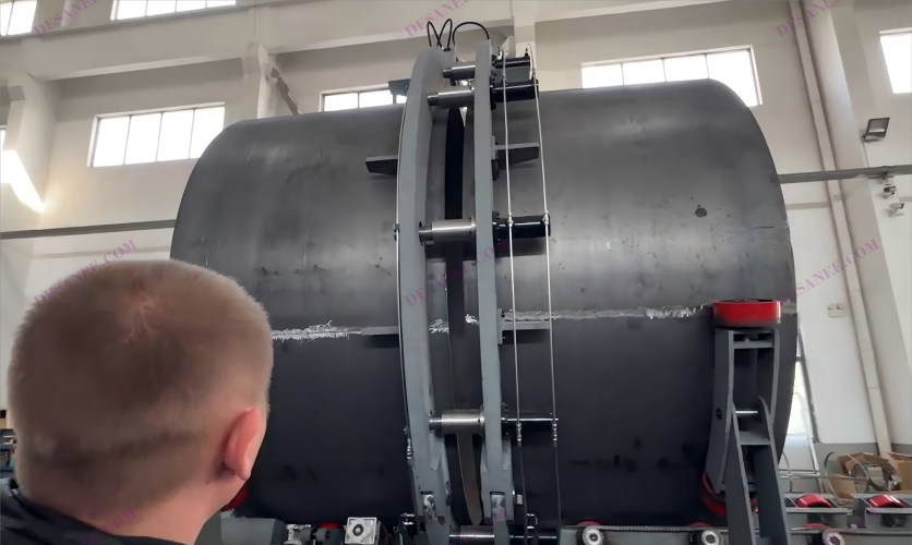
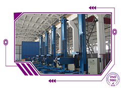
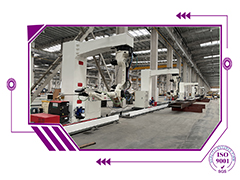
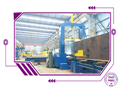
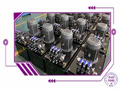
WELD MANIPULATOR WM4040 main parameter :
1.Summarize:
-
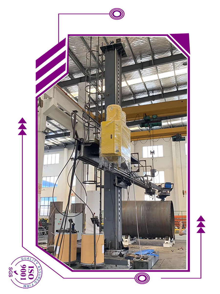
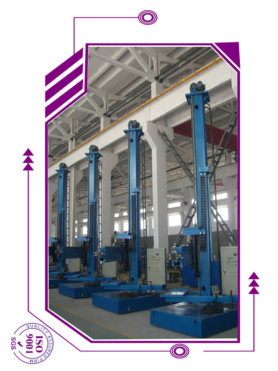
Column-boom WM4040 (movable and revolve) 1 set
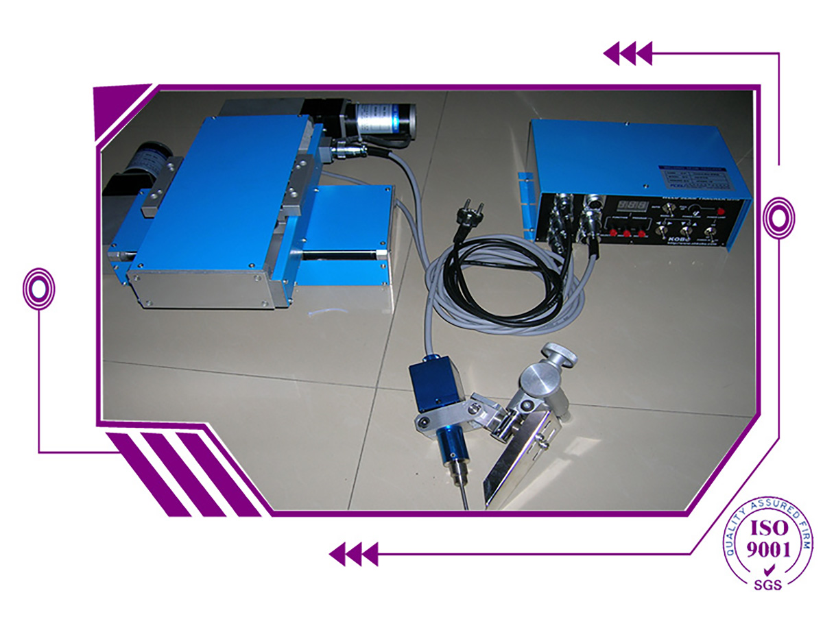
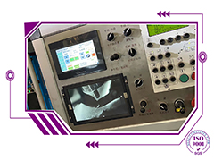
- KB-10 Seam Tracker(optional) 1 set
- DC-1000welding system (optional) 1 set
- Flux send and recovery system 1 set
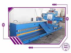
- SAR20 welding rotator 1 set (1P+1I)
2.Technical data
Column-boom: WELD MANIPULATOR WM4040
Structure: movable and revolve
Applicable vessel D: Φ630~4000 mm
Boom travel stroke: 4000 mm
Boom travel speed: 100-2000 mm/min (inverter)
Boom elevation stroke:4000 mm
Boom elevation speed: 1050 mm/min
Column motor-driven revolve angle: ±180°
Column manual revolve speed: manual
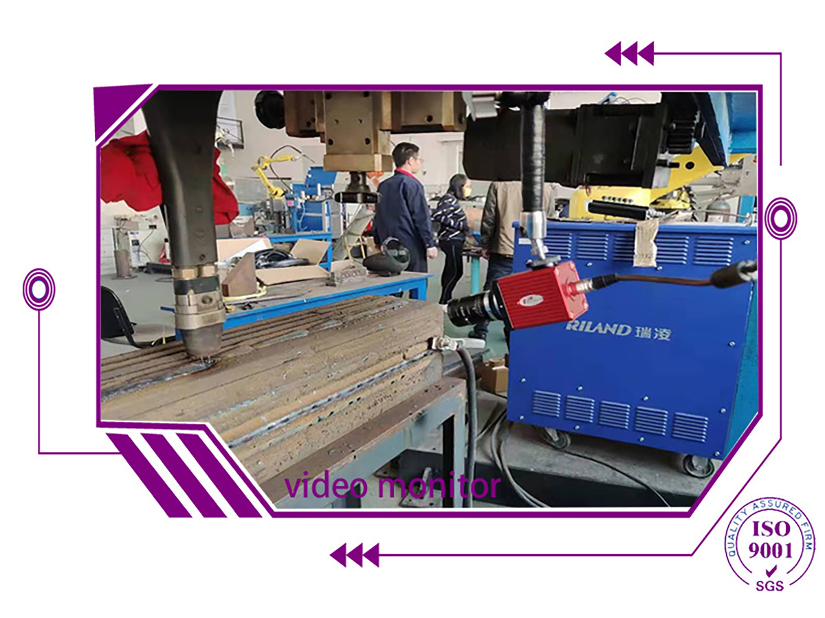
Seam-tracker:for weld MANIPULATOR
Model: KB-10
Testing range: 100 mm
Testing speed: 200 mm/min
Testing precision: ±0.3 mm
Loading: 100 kg
Power: AC220V
DC1000 SAW power with control box and wire feeder.
(CHINA AOTAI)
Rated welding current: 1000A
Idle voltage: 75V
Duty cycle:100%
Current range: 200~1000A
Wire D: 3~6 mm
Welding speed: 15~75 m/h
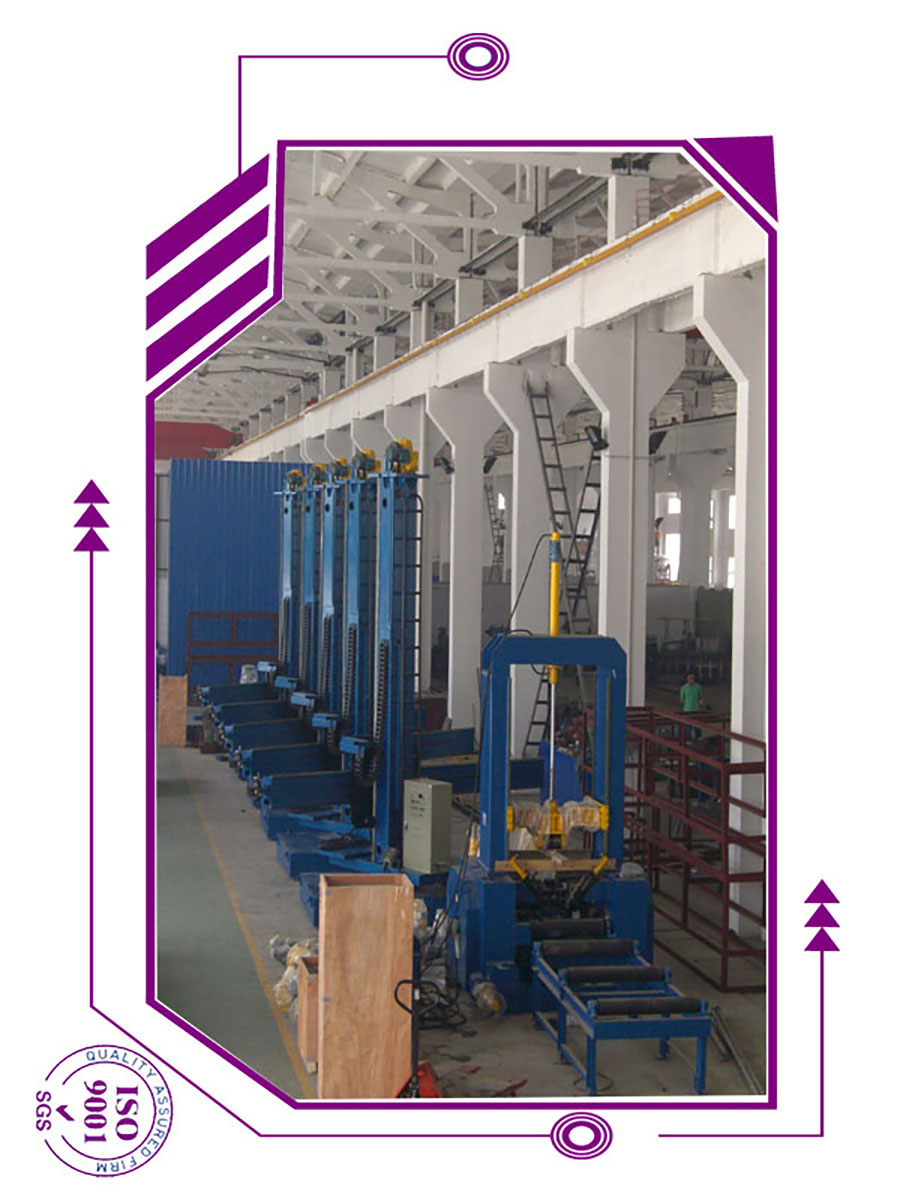
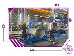
WELD MANIPULATOR WM4040 (manipulator) is used in petrochemical machinery, engineering machinery, wind power equipment, construction & bridge, shipbuilding, food & pharmaceutical and other industries
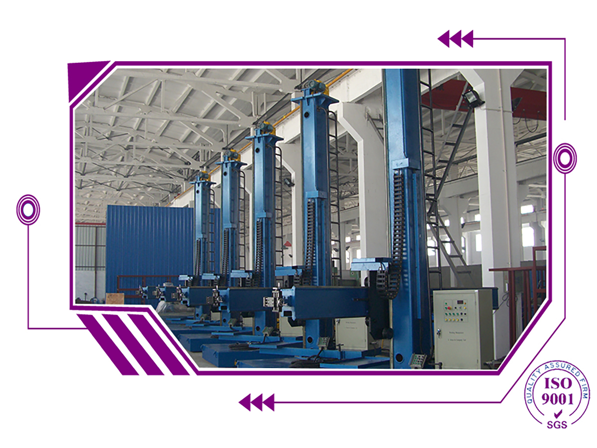
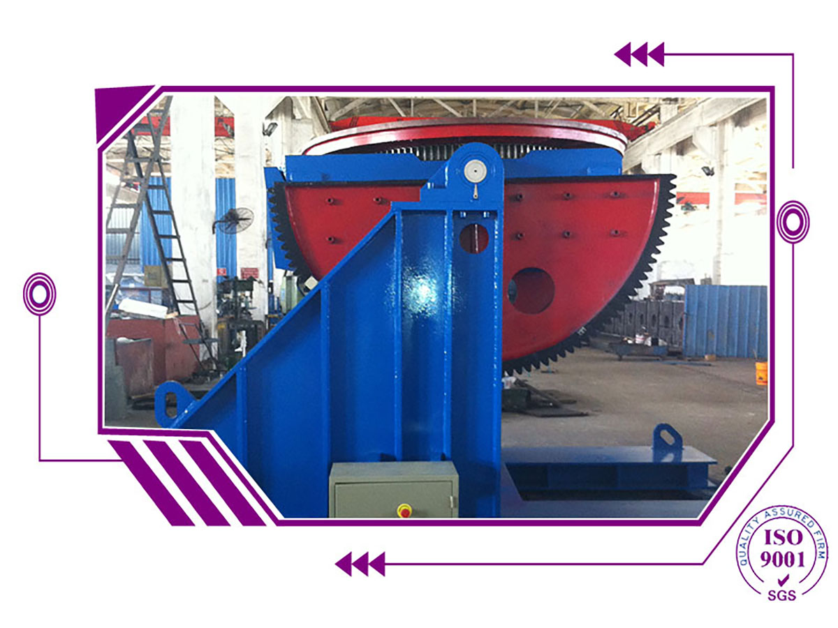
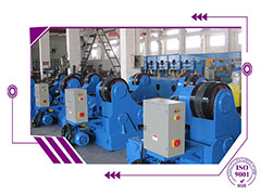
Welding rotator can apply in weld MANIPULATOR
3. Structure characteristics
This welding center mainly consists of column-boom、SAW and electric system.
3.1 Column-boom
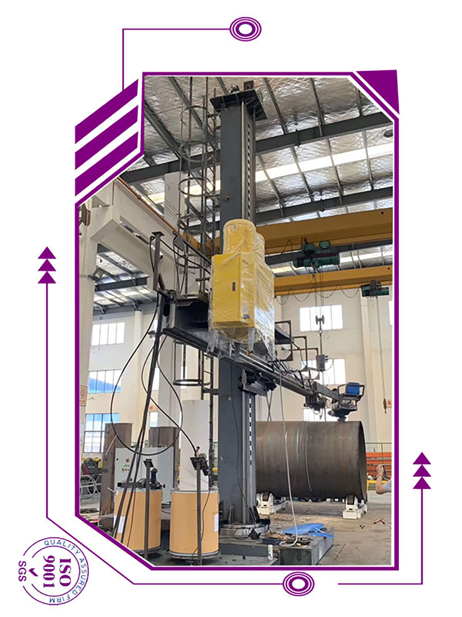
(1)This column-boom is mainly composed of:boom-elevate unit、boom travel unit、column revolve unit、movable trolley、cross-slides、column、boom、trolley、worktable and electric system;
(2) Both column and boom are rectangular-section beams, with double-rail, which is welded into shape、stress-relieved and mechanical machined finely, ensuring higher
precision;
(3)Boom-elevate unit is installed at column-top, composed of A.C. braking motor、reducer、chain and sprocket. It has counter-balance, making stable boom elevation. To prevent chains from incidental broken, ratchet-type anti-dripping unit on the column is used for safe and reliable operation.
(4) There are 8 sets of control rollers on the saddle along vertical and horizontal movement. Each set has 3 control rollers. These control rollers are contacted with rails of boom and column through 3-sides, of adjustable eccentric structure, with great loading capacity, making good contact between them and rail surface, ensuring smooth and no
shivering boom travel;
(5) Boom travel is realized with A.C. inverter motor through worm-gear reducer
driving gear-rack. Its speed can be adjusted within 100-2000mm/min through inverter,
(6) Column is fit onto trolley through heavy-duty cross-roll bearing. Column can be revolved within ±180° manual
