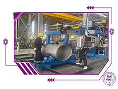
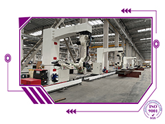
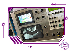
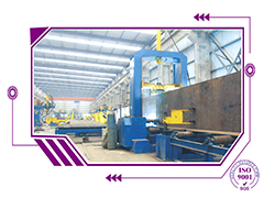
Sheet Metal Fabrication and Sheet Metal Box of Box Fabrication

Sheet Metal Fabrication and Sheet Metal Box of Aluminum Enclosure Box Fabrication

China Factory Custom Galvanized Stainless Steel Sheet Metal Aluminum Enclosure Box Fabrication or Sheet Metal Fabrication


Our service and our main product

【Sheet Metal Fabrication is used in petrochemical machinery, engineering machinery, wind power equipment, construction & bridge, shipbuilding, food & pharmaceutical and other industries


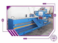
Our service including  laser cutting, CNC punching press, metal bending, steel welding, stainless steel automatic welding line, enclosure foaming, surface powder coating spraying ,assembly ,testing and so on.

Part Details (Sheet Metal Processing)Metal Materia: Stainless Steel sheet, Galvanized sheet, Aluminum Plate, Cold Plate, Iron plate, Pickling plateMachine:

Sheet Metal Fabrication


Features:Customized Design ;Sample Order Accepted
Short Delivery time; Competitive Prices
Long time quality Insurance;
Professional after-sale servicesTolerance: +/- 0.1mm or special requirements.Main Process:Sheet metal processing, Bending, Welding.Surface Finishing:Brushing, Polishing, Electrophoresis, Anodized, Powder Coating, Plating, Silk screen, Laser EngravingApplication:Auto /Moto Parts, Machinery Parts, Lighting Components, Hardware Accessories, Electric Motor ProductsPacking Details:EPE foam/ Anti-Rust Paper/ Stretch Film/ Plastic bag +CartonDelivery Time:Prototype sample 5-7days, Mass production: 14-21daysQuality Control System:Incoming inspection, process inspection, finished product inspection, delivery inspection

Sheet Metal Fabrication


   we also can privode all kinds electric box of SAR WR WP WM.  AND   is suitable for such making , pipeline installation unit's use of pipe fittings in the trade as the hydropower station , petroleum , chemical industry , shipbuilding ,etc.; It is pipe fittings making and pipeline that is it weld head tube end slope key equipment that bevelling processed to construct.


OEM Waterproof Electric Control Box Metal Enclosures Cabinets Outdoor

OEM Waterproof Electric Control Box Metal Enclosures Cabinets Outdoor  In order to ensure that electrical equipment supplied to USER conforms to DESAN's standards,  required to meet the following requirements.

1.

2      STANDARD SPECIFICATION AND LOCAL REGULATIONS


2.1        Equipment Standards

All materials and work shall comply with, and all equipment shall be designed, manufactured and tested, in accordance with the relevant Australian Standard Specifications or Codes of Practice, together with any amendments or other Regulations required by the Federal, State  or Local Authorities. Electric Control Box :Applicable standards include but are not limited to
 

AS1359 Rotating Electrical Machines
AS/NZS 2344 Limits of electromagnetic interference
AS2374 Power Transformers
AS 2381 Electrical equipment for explosive atmospheres
AS/NZS 3000 SAA Wiring Rules
AS/NZS 3008 Electrical installations - Selection of cables
AS 4024 Safe Guarding of Machinery
AS 60038 Standard voltages
AS/NZS 60079 Electrical apparatus for explosive gas atmospheres
AS 60204.1 Safety of machinery - Electrical equipment of machines - General requirements 
AS 60204.11 Safety of machinery - Electrical equipment of machines - Requirements for HV equipment for voltages above 1000 V a.c. or 1500 V d.c and not exceeding 36 kV 
AS/NZS 61000.3.6 Electromagnetic compatibility (EMC) Limits - Assessment of emission limits for distorting loads in MV and HV power systems
AS/NZS 61000.3.7 Electromagnetic compatibility (EMC) Limits - Assessment of emission limits for fluctuation loads in MV and HV power systems
AS 61508 Functional safety of electrical/electronic/programmable electronic safety-related systems
AS 61800 Adjustable speed electrical power drive systems
AS 62061 Safety of machinery - Functional safety of safety-related electrical, electronic and programmable electronic control systems 
   
  Western Power Corporation Technical Rules


Electric Control Box


2.2        Supply System

Electric Control Box  ,its Standard Power Supply System shall be 400V, 3 phase and neutral plus earth, 50 hertz and 230 volts, single phase and neutral plus earth, 50 hertz as per AS60038-2000.  Unless otherwise specified in project documentation all LV equipment supplied will be suitable for connection to this voltage. High voltage supply levels shall be approved in writing by Bradken prior to Supplier committing equipment.

2.3        Enclosures

All enclosures shall be industrial dustproof, fully protected indoor/outdoor, weatherproof, tropicproof, flameproof, or increased safety etc. as required by the particular hazardous area classification into which the equipment is to be installed.

Indoor enclosures situated in Control Rooms shall have a minimum degree of protection IP54.  Enclosures located outdoor or in plant areas shall have a minimum degree of protection IP56.

2.4        Control Voltages
The preferred Control Voltage shall be 24V DC.

      1. Circuits shall be fail safe i.e. de-energised to trip.
      2. Alarm initiating contacts shall be normally closed and energised open under 'non' alarm conditions.
      3. Indication lamps shall be  extra low voltage  High intensity LED
      4. Preferred Current Transformer secondary rated current shall be 1 amp except for specialised applications requiring other values.


3      SWITCHBOARDS AND DISTRIBUTION BOARDS


In general, Electric Control Box  switchboards and distribution boards are to be provided in accordance with relevant sections of AS 60204- Safety of machinery - Electrical equipment of machines, except where the following requirements are more stringent.
 
3.1        Switchboards

All switchboards shall be free standing, metal clad, dust proof enclosures with front access only. LV switchboards to be of Form 3b condtuction - segregation of busbars, incomer unit and functional units.

Main switchboards shall be fitted with a suitably rated incoming circuit breaker fitted with electronic overload and earth leakage protection. Undervoltage trip shall also be included if warranted by load types.

A single voltmeter switched between phases and phase to neutral together with three ammeters fitted with maximum demand indicators plus a power factor and kilowatt hour meter shall be fitted to all main switchboards. Alternatively a single digital meter providing these functions such as an Allen Bradley Powermonitor is acceptable.  A lockable hinged panel shall be provided for the mounting of the above instruments.  Where applicable a C/T chamber to comply with the local supply authorities requirements shall be provided.

Nilsen or GEC combined fuse switch units shall be used for all subcircuit supplies as a minimum. Suitably fault-rated moulded case circuit breakers are acceptable where more procise protection is required.

A spacious outgoing cable compartment fitted with a neutral bar with adequate take offs and earth bar shall be provided.

3.2        Distribution Boards

3.2.1     All distribution boards shall be metal clad and suitable either for wall mounting or floor mounting depending on size. Wall mounted panels shall be positioned such that the top of the panel is 2 metres above floor level.  Boards shall have a lockable handle. Boards shall be fitted with hinged internal escutcheon with fixing tool access.
              3.2.2     Top entries shall not be made to outdoor distribution boards, and where possible, all entries shall be from below.
              3.2.3     Each board shall be labelled with the appropriate board designation as per single line diagram.
              3.2.4     Distribution boards shall be fitted with circuit breakers of relevant fault level. Where miniature circuit breakers are installed they shall be equal to SAFE-T or better. Individual circuit breakers are to be lockable in the off position.

      1. Each board shall be complete with a suitably rated isolating switch, together with the required number of ways plus 20% spare spaces.  Isolating switches to be interlocked to the escutcheon so as to allow the escutcheon to be opened only in the "Off" position or by use of a tool. Isolating switch to be lockable in the off position.
      2. Opening of door shall not expose live parts.
      3. All busbars shall be P.V.C. coated in appropriate phase colours, black for neutral. The neutral bar shall be insulated from earth.
      4. All single phase GPO circuits shall be protected by means of a core-balance earth leakage circuit breaker.
      5. All distribution boards shall be fitted with a maximum demand indication ammeter fitted to B Phase.
      6. Each board shall be provided with a fully documented, non-deteriorating legend, mounted inside the door.
      7. No earth - neutral connections shall be made at distribution boards.
      8. Doors and escutcheons, fitted with instruments and electrical devices, shall be connected to the main case or cubicle with a 4mm2 minimum sized flexible earthing bond conductor.


3.3        Motor Starter Panels

              Where a group of motors are part of a single machine or plant the motor starters shall be enclosed in a single motor control centre. The MCC is to be of Form 3b segregation.

            if Electric Control Box , Motors rated below 30KW shall in general be started DOL. 30KW and above the motor starters will be selected to suit the particular application.

4      CONTROL PANELS


In general, control panels are to be provided in accordance with relevant sections of AS 60204- Safety of machinery - Electrical equipment of machines, except where the following requirements are more stringent.

4.1        General - Main Control Panels

All control panels shall be metal clad and suitable either for wall mounting or floor mounting depending on size. Wall mounted panels shall be positioned such that the top of the panel is 2 metres above floor level.  Boards shall have a lockable handle.. Where items such as instruments, meters, push buttons, selector switches, etc. are fitted to the panel or door, the dustproof and/or weatherproof quality shall be maintained.

Doors and escutcheons, fitted with instruments and electrical devices, shall be connected to the main case or cubicle with a 4mm2 minimum sized flexible earthing bond conductor.

4.2        General - Small Control Panels

Requirements as for 4.1. Small control panels such as field mounted selector/control stations, junction boxes and lighting fitting control boxes need not be fitted with a lock.  However, access shall be gained only by a person going through a positive deliberate action such as removing screws or nuts and bolts, etc. All operator controls and indication shall be mounted on the front panel.  Access doors and panels larger than 0.1 metre square shall be hinged.

4.3        Pushbutton Stations

             4.3.1     In general, motors shall be provided with the means of starting and stopping, both from a control station located adjacent to the motor and from a remote control panel where applicable. The Supplier shall state any additional and/or alternative control which may be required from other positions.
              4.3.2     A local control station, equipped with: start and stop buttons; a local/remote mode selection switch;, shall be mounted adjacent to the motor. Refer to section 5.4.2 for motor isolators. 
              4.3.3     Motor emergency stop pushbuttons shall be latching type. The "normally closed" contacts shall be wired in series with the motor contactor coil.
              4.3.4     A second set of contacts shall be provided for indication of latched emergency stops.

4.4        Indication Lamps
              Lens colour shall be -:

  • Red                              "MAJOR ALARM" or "DANGER"
  • Green                          "ON" or "RUN"
  • Blue                             "AUTOMATIC SEQUENCE"
  • Amber                          "MINOR FAULT"
  • White                           Other Conditions "PLANT READY" etc.


4.5        Push Buttons
              Button colours shall be:

  • Green                          "Start", "Close" or "On"
  • Red                              "Emergency Stop", "Trip" or "Off"
  • Black                            "Reset", "Normal Stop" or other conditions


4.6        Meters

Where meters are required, the minimum size meter shall be 96mm squared. Meters shall be scaled such that maximum operating position is within 75-80% of Full Scale. All ammeters shall be calibrated for a minimum of five times over scale with a withstand of eight times over scale.

Meters should be easily readable from a standing position and should be mounted between 1.5 and 1.8 metres above ground when mounted on a vertical surface.

Meters mounted on a control desk should be angled up so that they are easily readable from both the sitting and standing position.

4.7        Controls and Cable Entries

Requirements as for 3.2.2.

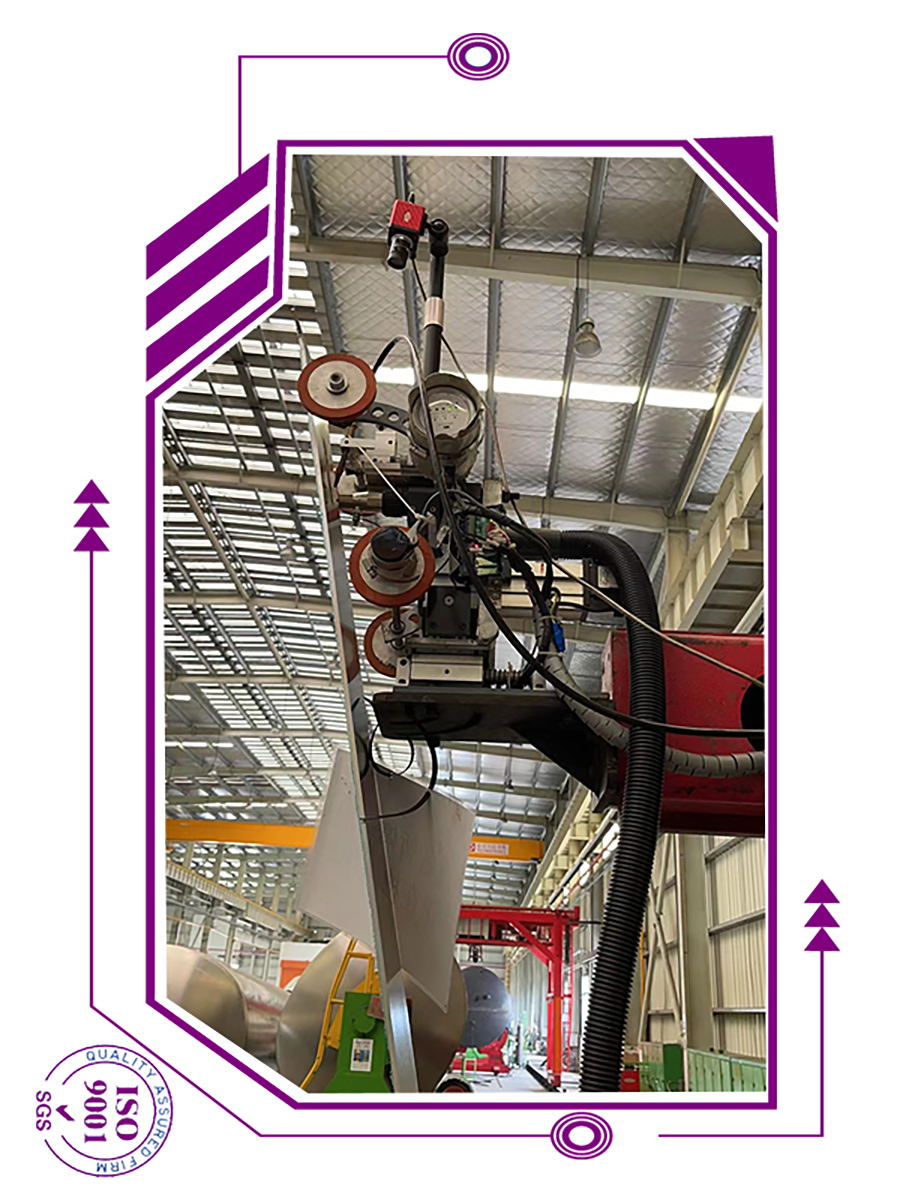
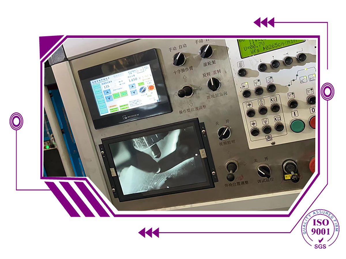
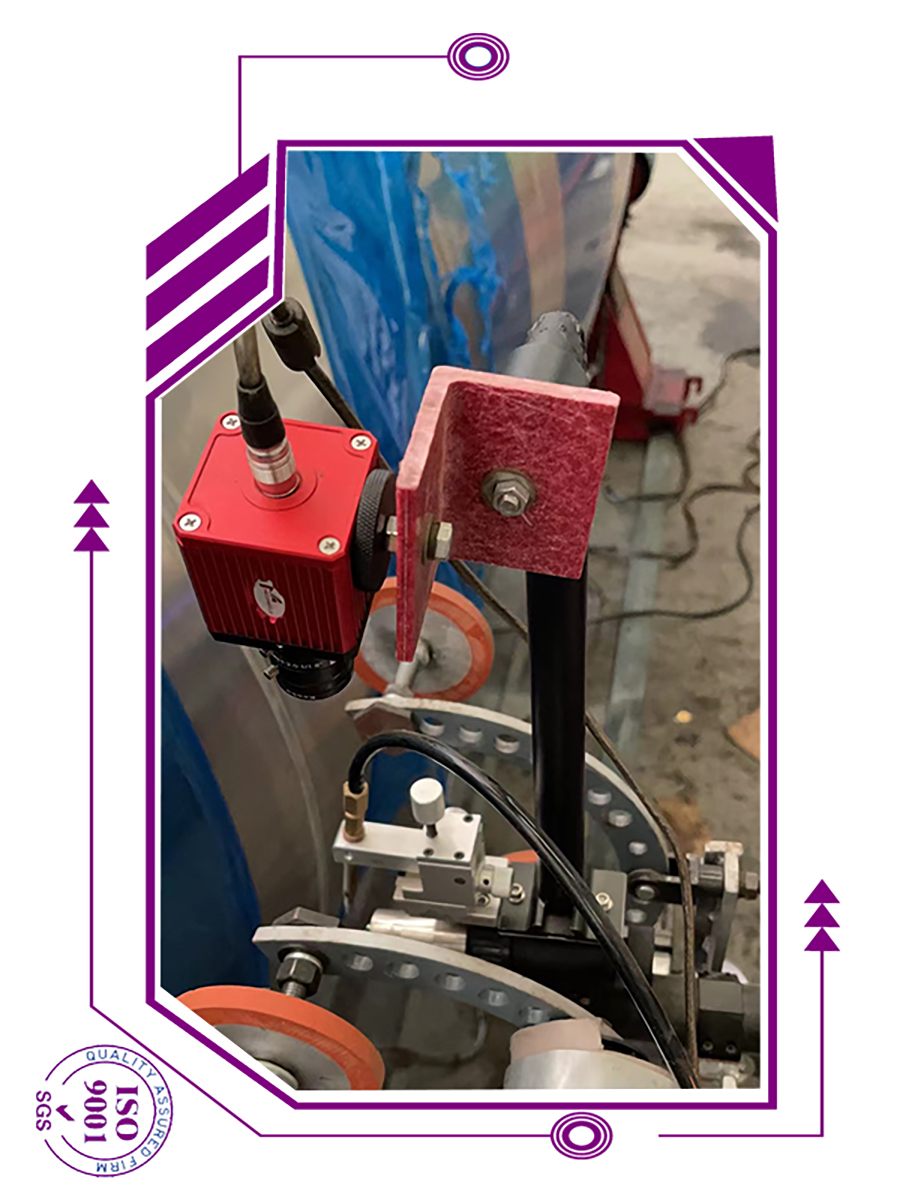
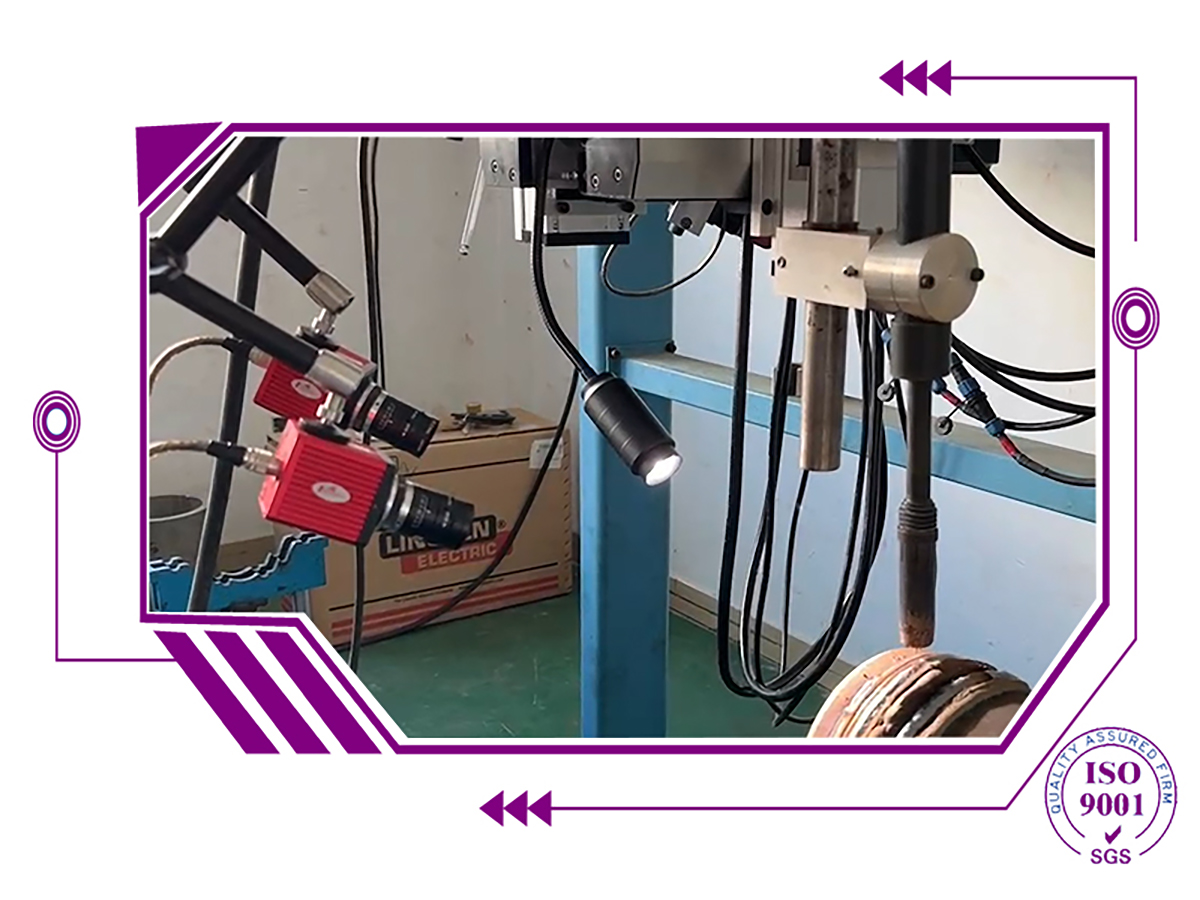
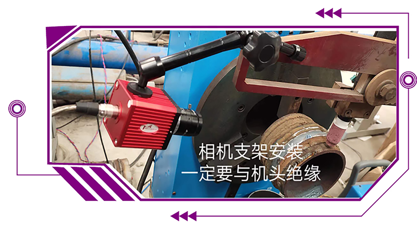
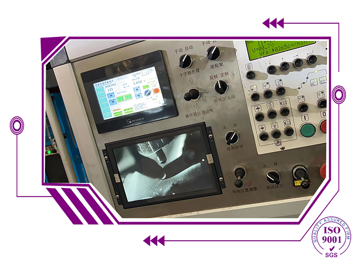
Welding Camera Apply in TIG Plasma Welding and Monitor for Welding

Welding Camera Apply in TIG Plasma Welding and LCD Camera Monitor for Welding Line Dynamic Range Image + 140 dB, The Ds30 Can Acquire Images with a Great


High Dynamic Range (HDR)

With a dynamic range image + 140 dB, the DS30 can acquire images with a greater range of tonal detail than any standard camera.
This is particularly important for welding processes where there is a very bright light source in the image that needs to be seen in great detail as well as the darker surrounding background features.

Color When You Need It

With HDR color imaging, the DS30can acquire color images for various welding processes, such as GTAW, where color provides extra information such as: the boundary of the Heat Affected Zone, oxidation of the melt pool and tip, and shielding gas presence. The very bright weld arc can be seen in color without saturation as well as its darker surround- ing background features.

welding camera

Welding Camera

welding camera

Welding cameras traditionally have been employed to aid automated or mechanized welding of inaccessible joints and ensure the integrity of critical welds.
      Cameras are practical tools for many other welding applications, too, now that recent advances in electronics have enhanced the image quality and reduced the price of such equipment.
Welding cameras are particularly useful for improving working conditions, weld quality, set-up speed, positioning accuracy, and facilitating quality assurance.
++ Welding Cameras Use In Automated Welding Procedures
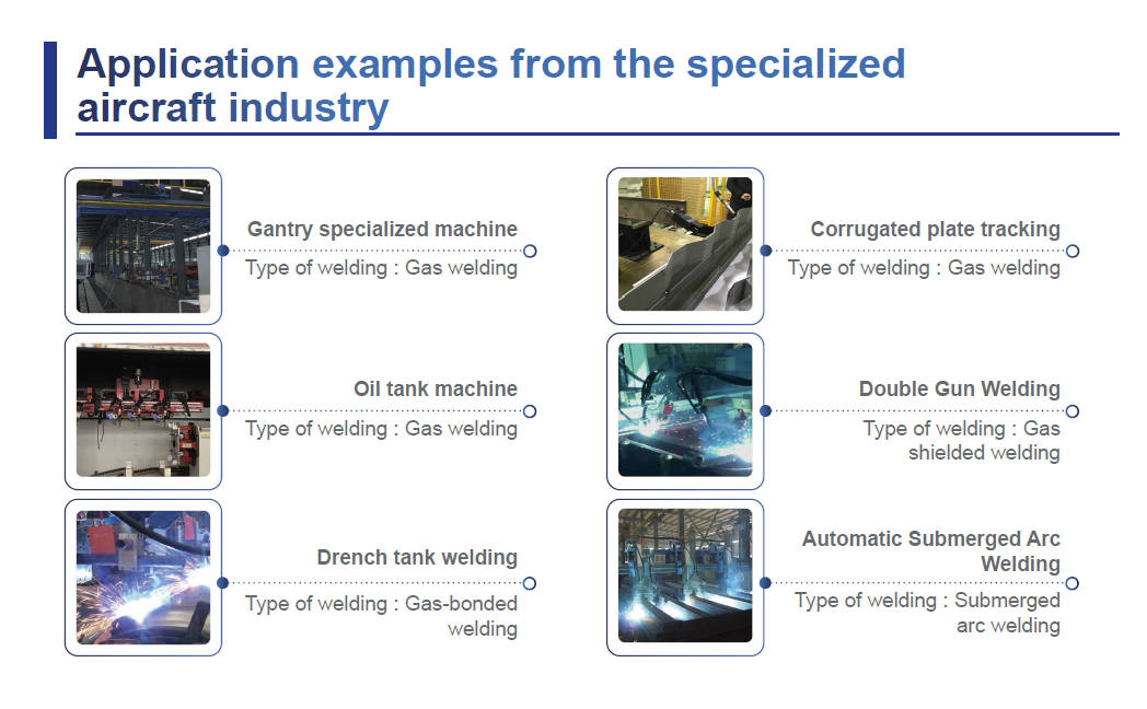
From job-shop manual welding to push-button automated welding, fabricators employ a wide range of automation techniques to improve productivity and weld quality, as well as to ensure a welder's health and safety.  Relatively simple circumferential and linear joint-seams are often welded using positioners, rotators, column and booms, seamers, lathes, tractors, orbital welders, etc. Such equipment may use sensors to automatically control the process (automated welding), or the operator may manually control the movement and/or torch (mechanized welding). 
In either case, a clear view of the weld pool can significantly benefit the welding operation.
++ Applications and Benefits of Cameras in Automated Welding
The use of camera systems in automated welding arose from necessity.  Welding in hazardous environments subject to nuclear radiation, vacuums, lasers, argon, or water entails the use of welding cameras to control the torch head remotely and wire feed positions as well as to monitor the welding process. Welding cameras provide similar benefits in automated applications with restricted access (including bore cladding, orbital welding, and welding at height) or joints subject to preheating
++ Weld Quality Inspection In Real Time
In addition to positioning the torch before and during welding, cameras may be used as a real-time post-weld inspection tool by positioning the camera for views of the solidifying weld pool.In many cases, welding cameras are applied to monitor the welding of critical joints or expensive materials. For these applications, the cost of failure is significant, and the ability to take pre-emptive action is essential. 
++ Improving Welding Speed And Accuracy
However, welding cameras are no longer restricted to the most sensitive and expensive welding operations. Advances in camera electronics have improved image quality and reduced purchase costs, such that welding cameras now prove beneficial to many more automated welding applications. For example, a magnified view of the electrode and torch helps improve the set-up speed and accuracy of automated micro TIG and PAW, dabber TIG, and tube mill applications.  The performance of mechanical joint tracking systems is enhanced by camera supervision. Cameras applied to carriages facilitate welding upside down, at height, inside confined spaces, and around circumferential joints. 
Automated systems with multiple weld-torches, like those used to manufacture turbine shafts, welded I-beams, spiral tubes, and tanks, may be effectively monitored and controlled from a single console.


electrode submerged arc surfacing and electrode electroslag surfacing

1. Preface of electrode electroslag surfacing:

The inner surfaces of reactors, reactors and thick-wall pressure vessels of nuclear power plants in the petrochemical industry require large area surfacing welding of stainless steel linings that are resistant to high temperature, oxygen and hydrogen sulfide corrosion. In the 1970s, in this field, a large number of domestic and foreign use of electrode submerged arc surfacing (SAW) technology. The width of the band pole is also developed from narrow band to 60mm, 90mom, 120mm, 150mm broadband direction. This technology has made great progress in dilution rate and deposition speed compared with submerged wire arc welding.

However, with the increasing size and high parameterization of pressure vessels, surfacing welding technology has been developed in a higher quality and more efficient direction. electrode electroslag surfacing ,Electroslag surfacing technology with electrode has been developed rapidly and widely in recent years because of its advantages of higher production efficiency, lower dilution rate and good weld formation than that of submerged arc with electrode.

Electrode electroslag surfacing is a highly efficient surfacing method, which is divided into two types: electrode submerged arc surfacing and electrode electroslag surfacing. Due to the use of thin plate type wide electrode and high welding current, so its melting speed is more than ten times to dozens of times of various monofilm welding melting speed.

2. One of the differences between Submerged Arc Strip Cladding (SASC) and common submerged arc welding SAW is that the welding wire is changed to a strip electrode. The arc is created between the strip pole and the workpiece. Flux flux is used to form a slag to protect the weld pool and help form a smooth weld surface.

electrode electroslag surfacing

electrode electroslag surfacing


3. Electrode electroslag welding

Electrode electroslag surfacing is the resistance heat caused by the liquid slag as a heat source. First, the arc is ignited between the electrode and the base material. The heat generated by the slag melts the surface of the substrate, and the edge of the electrode is immersed in the slag and flux. After the arc heat melts the flux to form the slag pool, the arc heat transitions to the resistance heat of the slag. The melted metal has a high density and sinks to form a liquid metal molten pool. The slag has a low density and floats above the molten pool. The slag pool is covered with the metal molten pool to protect the metal molten pool. Then the electrode continues to melt, the liquid metal and slag in the molten pool are rising continuously, and the lower liquid metal far away from the heat source is cooled and condensed into a surfacing layer.

electrode electroslag surfacing


Compared with submerged arc surfacing with pole, ESW or ESSC has the following characteristics:

ALSO IS electrode electroslag surfacing.

(1) The melting rate was increased by 60%-80%. (See picture below)

(2) Because the penetration is very shallow (about 10% to 15% dilution rate), only half of it is diluted to the base material.

(3) Welding low voltage (24-26 V).

(4) Large current and current density (60mm wide welding belt through the current is l000-1250A, the corresponding current density is 33-42 A/mm2), especially the high-speed flux allows the welding current to exceed 2000A, the corresponding current density is 70 A/ram2.

(5) The welding speed is increased (50%-200%), resulting in an increase in the coverage area.

(6) The heat input is roughly the same.

(7) Low flux burn loss (about 0.4-0.5kg /kg strip).

(8) The curing rate of ESW welding weld metal is very low, which is conducive to porosity escape and reduce porosity defects. Oxygen can escape from the molten electroslag pool to the surface; The metal surface of the surfacing layer is quite clean, which reduces the tendency of thermal cracking and intergranular corrosion from a metallurgical point of view.

In the practical application of industrial production, electrode electroslag surfacing is very important that the weld surface of the product has a higher melting rate and a lower dilution rate than the base metal. Submerged arc surfacing with electrode has been widely used in large surface surfacing, but electroslag surfacing technology is gradually taking the dominant position. 

Electrode electroslag surfacing  mainly used in petrochemical machinery, engineering machinery, wind power equipment, construction & bridge, shipbuilding, food & pharmaceutical and other industries


3D Laser Weld Tracking Sensors for TIG Plasma MIG Welding

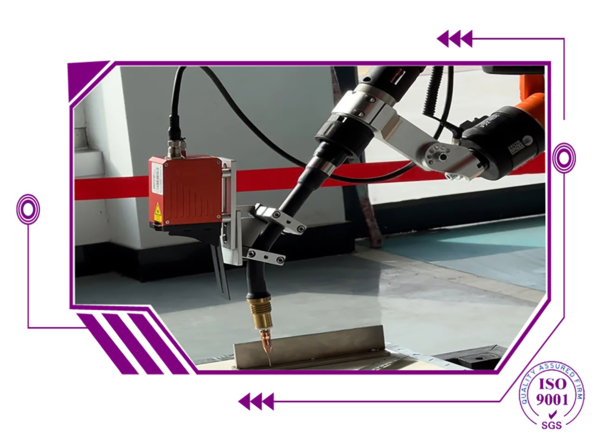
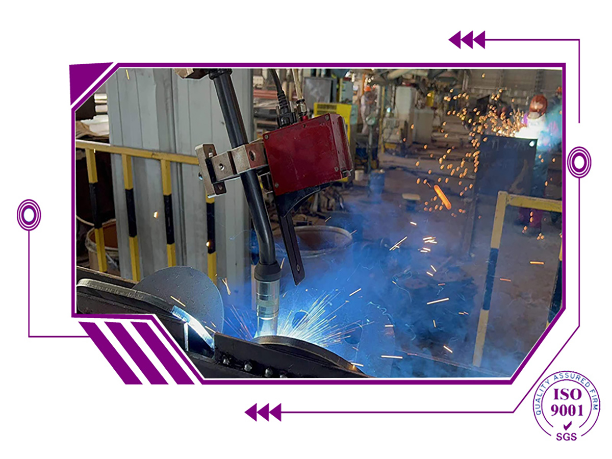
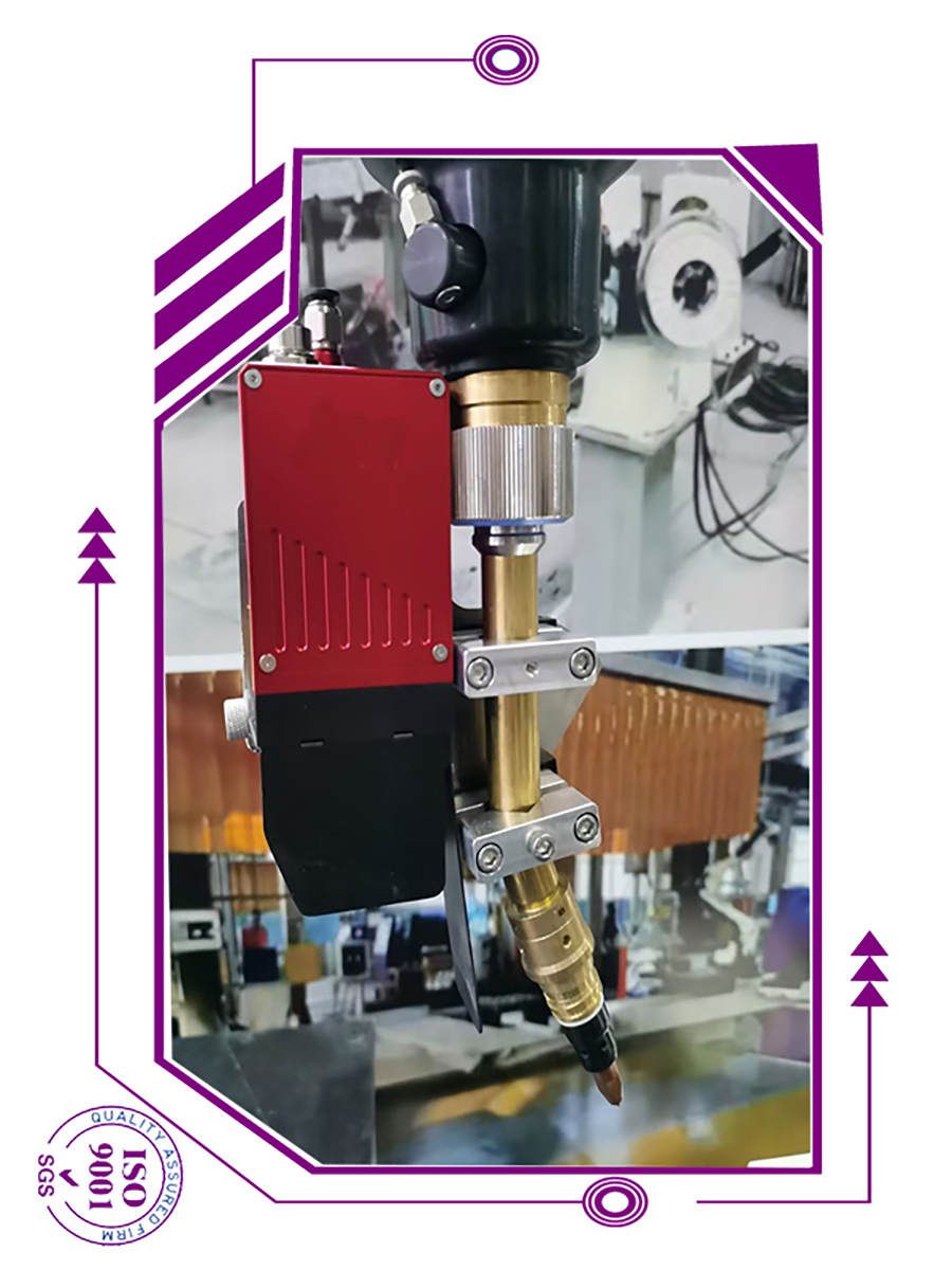
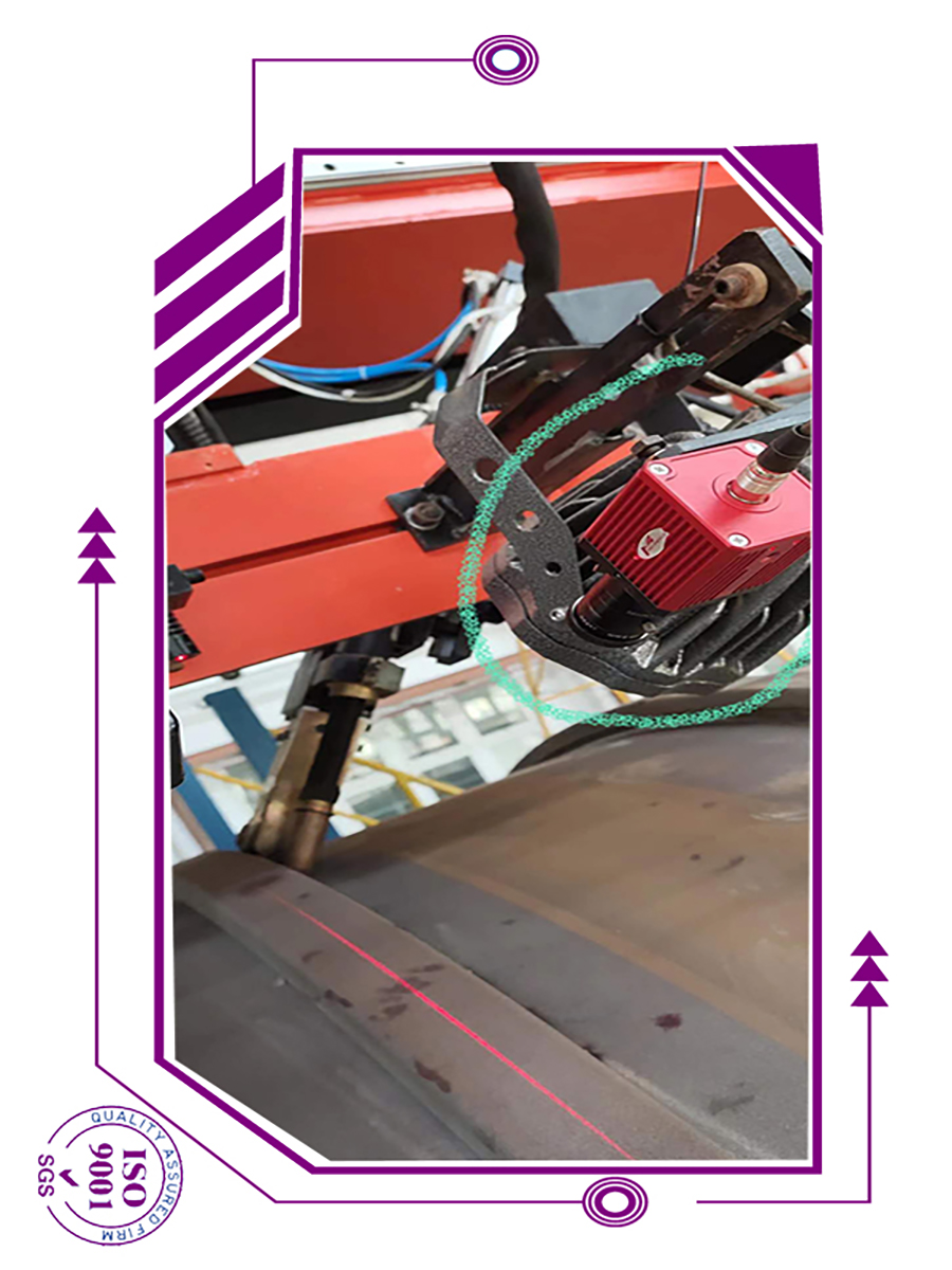
Laser Weld Tracking is one special welding auxi machine,

Laser Weld Tracking

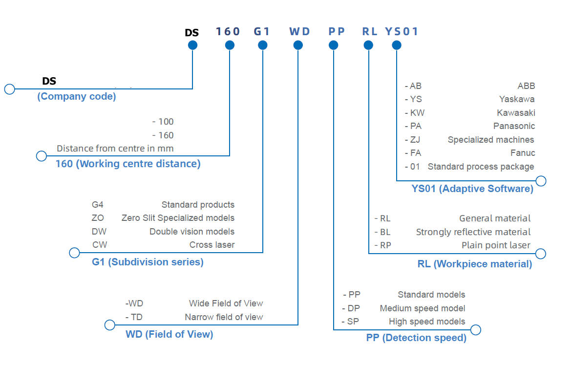
we can provide :  3D Laser Weld Tracking Sensors for TIG Plasma MIG Welding Monitor and Tracking Seam Laser Seam Tracking Product Used in TIG Welding Robot Argon Arc Welding

DS laser seam tracking product used in TIG welding robot with filler wire
    Tactile or laser-guided weld seam trackers are an automated method for accurately tracking the weld seam.  Various modes allow for the tracking of many different joint designs and situations.

Laser Weld Tracking

3D laser weld tracking sensors , DS company provides customers with 3D sensors, automatic systems exempt from programming, welding robots and completed solutions for welding specialized machine systems. Focusing on improving our own R&D and innovation capabilities, owning unique and innovative ideas in the fields of optics, electronic hardware and algorithms, and aspires to design optimal solutions for complex welding operations 3D Laser Weld Tracking Sensors for TIG Plasma MIG Welding

3D Laser Weld Tracking Sensors for TIG Plasma MIG Weldingis used in petrochemical machinery, engineering machinery, wind power equipment, construction & bridge, shipbuilding, food & pharmaceutical and other industries


Laser Weld Tracking

Sensor characteristics
• Compact and small
Highly integrated, compact and easy to disassemble
Built-in controller, small size and low power consumption
• Well-protected design
Reliable internal structure design, suitable for complex and harsh industrial production environments
• Strong real-time tracking
Highly efficient image detection algorithm, high speed image processing speed; unique tracking and calibration
algorithm to achieve real-time tracking
• Strong anti-interference
Built-in air cooling / air knife system; professional electrical protection design can adapt to various high frequency
electromagnetic and electrostatic industrial production environmen
• Flexible and versatile
Plug and Play anytime
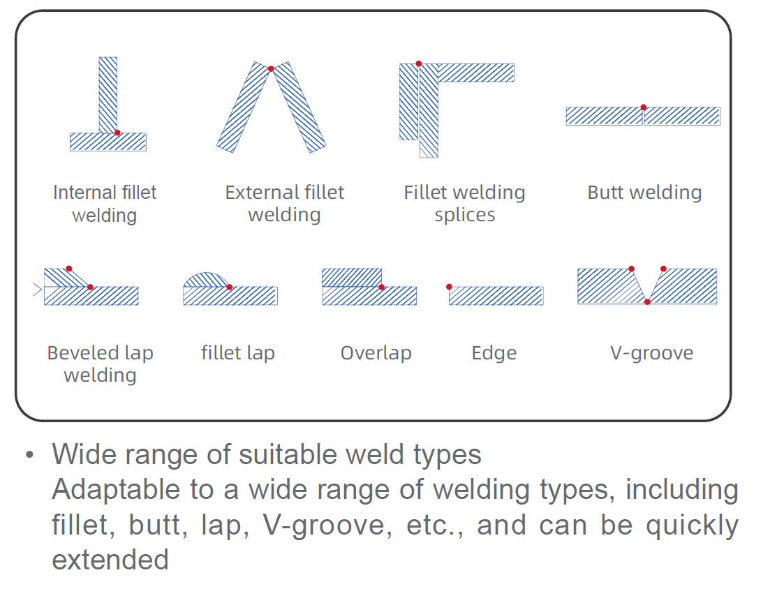
Full weld support
Customised detection algorithms for non-standard welds
Communication protocols for more than 40 brands of robots
Different resolutions apply to both laser welding and MIG welding

• Simple operation
Full Chinese software interface, with a flowing parameter setting process and detailed instruction menus, even
non-experts can quickly get started

System working principle
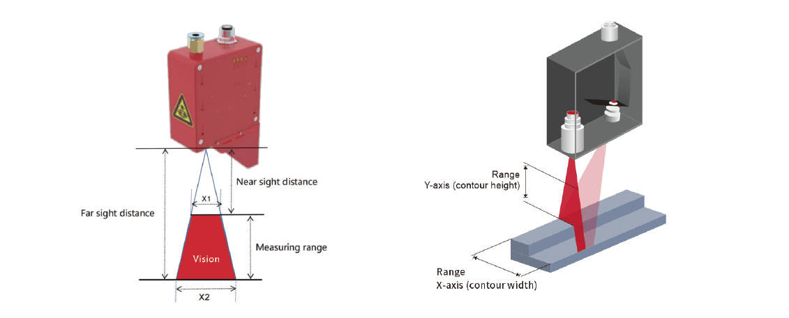
   A laser is used as a light source to emit a certain wavelength of laser light onto the surface of the weld, forming a laser strip which is received and imaged by a HD camera at another location. After a series of algorithms, the 3D features of the weld are converted into images, generating structured information about the position and shape of the object being measured. This provides the robot with the path it needs to guide the welding process.
It is characterised by high accuracy, contactless and high speed.


Laser Weld Tracking